ALL CATEGORIES
COMPANY INFO

Delivery Fee : $0.00
Quantity :
| Part NO. : | DCFBG-series |
| Datasheet : |

|
| Availability : |
VGM4500-FM06
Variable Gain EDFA Module (without
MSA)
C-Band DWDM VGA Module without MSA

Description
a. Idealphotonics
VGM4500-FM06 series is a next generation variable gain optical amplifier
module, which with the most excellent performance and most completes functions
in the market. It adopts nowadays most excellent optical performance, most
advanced electronic technology and most complete software functions. Remarkable transient suppression control
technology and heat management control technology let many complicated optical
functions achieved. It is the most versatile multifunction optical amplifier in
the market.
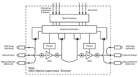
b. This next generation variable gain amplifier module is composed with two
stages amplifier: variable gain pre-amplifier (PA) and variable gain booster
amplifier (BA). The gain of these two stages amplifier can be independently set
in a certain range. There is a connector between the two stages amplifier,
which used for mid-stage access, such as optical Add-Drop module (OADM), dispersion
compensation module (DCM) and others optical modules.
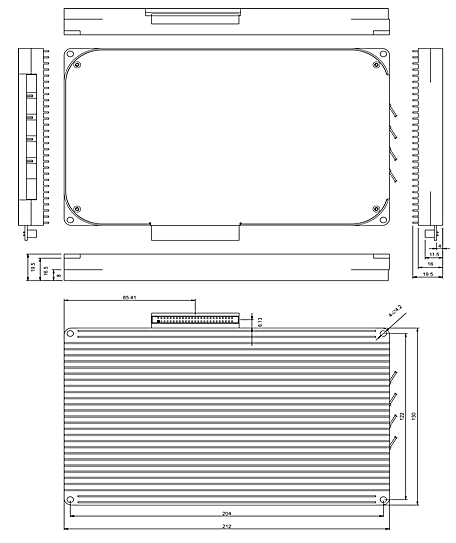
c. VGM4500-FM06 adopts 130×212×19.5mm (including heat sinks) ultra-thin
appearance; signal unit +5VDC power supply, low consumption.
d. VGM4500-FM06 is a device
without Mid-stage Access, which according with various communication technology
requirements of C-Band 44 or 88 channels DWDM system, widely used in long
distance and ultra-long distance transmission network. Since its complete
functions, it can be used as line amplifier, pre-amplifier, booster amplifier.
Applications
• Long-distance or ultra-long haul network between the city
• Line amplifier, Pre-amplifier, Booster, Add/Drop amplifier
Features
• Nest-generation
Variable Gain Amplifies Module
• Without Mid-stage Access Version
• Accord with the various communication technology requirements of C-Band 44 or
88 channels DWDM system
• Adopt latest total integration electronic transient control technology
• Adopt digital control technology which can adapt to heat management.
• Saturation large output power optional: 18dBm, 20dBm, 23dBm,24dB,AGC, APC,
ACC working mode
• Optical monitoring
channels optional: OSC Add/Drop
• Carrier-class security and reliability
• Ultra-thin appearance 130×212×19.5mm(including heat sinks)
• Low power consumption
• Excellent cost performance in area
Dimensions

SOFTWARE FUNCTIONS, MOITORS AND ALARMS
|
Functions |
In service firmware upgrades |
|
Auto shut down(AGC) |
|
|
Gain control mode with automatic power limiting |
|
|
Gain tilt control |
|
|
Independent stage mode (on variants with Mid-stageaccess) |
|
|
Output power control mode |
|
|
Pump current control mode |
|
|
Eye-safe power mode |
|
|
Non-volatile event log |
|
|
Monitors |
Total input power |
|
Total output power |
|
|
Optical backreflection |
|
|
Pump status |
|
|
Module temperature |
|
|
Alarms |
Loss-of-signal alarm |
|
Low output power alarm |
|
|
Module temperature alarm |
|
|
Pump temperature alarm |
|
|
Pump bias alarm |
|
|
Excess backreflection alarm (optional) |
OPTICAL/ELECTRICAL SCHEMATIC

50 PIN Interface DEFINATION
|
Pins |
Description |
Pins |
Description |
|
1 |
Power supply |
2 |
Power supply |
|
3 |
Power supply |
4 |
Power supply |
|
5 |
Power supply |
6 |
Power supply |
|
7 |
Ground |
8 |
Ground |
|
9 |
Ground |
10 |
Ground |
|
11 |
Reserved ( do not connect ) |
12 |
Output Reflection Alarm |
|
13 |
Ground |
14 |
Resent input |
|
15 |
Serial input |
16 |
Serial output |
|
17 |
Pump Current Alarm |
18 |
Stage 1 input LOS alarm |
|
19 |
Ground |
20 |
Ground |
|
21 |
Reserved ( do not connect ) |
22 |
Reserved ( do not connect ) |
|
23 |
Reserved ( do not connect ) |
24 |
Reserved ( do not connect ) |
|
25 |
Ground |
26 |
Reserved ( do not connect ) |
|
27 |
Stage 2 input LOS alarm |
28 |
Ground |
|
29 |
Stage 2 output/Gain alarm |
30 |
Ground |
|
31 |
Ground |
32 |
Ground |
|
33 |
Case temperature alarm |
34 |
Stage 1 output / Gain alarm |
|
35 |
Pump temperature alarm |
36 |
Pin is absent ( Polarization key ) |
|
37 |
Amplifier disable input |
38 |
Output Power mute input |
|
39 |
I2C SCL ( Optional ) |
40 |
I2C SDA ( Optional ) |
|
41 |
Ground |
42 |
Ground |
|
43 |
Ground |
44 |
Ground |
|
45 |
Power supply |
46 |
Power supply |
|
47 |
Power supply |
48 |
Power supply |
|
49 |
Power supply |
50 |
Power supply |
|
Performance |
Index |
Supplement |
||||
|
Min. |
Typ. |
Max. |
||||
|
Optic feature |
Wavelength work range |
(nm) |
1529.16 |
|
1563.86 |
ITU 88CH |
|
Input power range1) |
(dBm) |
35 |
|
+3 |
VGM4518 Typ. |
|
|
35 |
|
+3 |
VGM4520 Typ. |
|||
|
-40 |
|
0 |
VGM4523 Typ. |
|||
|
40 |
|
0 |
VGM4524 Typ. |
|||
|
Gain range 2) |
(dB) |
18 |
|
30 |
G30 Typ. |
|
|
23 |
|
35 |
G35 Typ. |
|||
|
29 |
|
41 |
G40 Typ. |
|||
|
12 |
|
24 |
G25 Typ. |
|||
|
Max. output power3) |
(dBm) |
|
|
18 |
VGM4518 |
|
|
|
|
20 |
VGM4520 |
|||
|
|
|
23 |
VGM4523 |
|||
|
|
|
24 |
VGM4524 |
|||
|
Gain flatness |
(dB) |
|
0.7 |
1.0 |
Peak-to-peak |
|
|
Noise figure |
(dB) |
|
5.0 |
5.9 |
Max gain |
|
|
Polarization dependence loss |
(dB) |
|
|
0.3 |
|
|
|
Polarization dependence gain |
(dB) |
|
|
0.3 |
|
|
|
Polarization mode dispersion |
(ps) |
|
|
0.3 |
|
|
|
Pump leakage power |
(dBm) |
|
|
30 |
|
|
|
Return loss4) |
(dB) |
40 |
|
|
UPC |
|
|
Optical supervisory channel wavelength ranges |
(nm) |
1500 |
1510 |
1520 |
|
|
|
feature Transient |
Transient setting time |
(μs) |
|
|
500 |
16dB Add/Drop |
|
Transient gain changes |
(dB) |
|
|
0.5 |
|
|
|
efl |
Communication interface |
|
RS232 |
|
||
|
Fiber type |
|
Coming SMF-28TM or equivalent |
|
||
|
Pigtail buffer diameter |
(μm) |
|
900 |
|
|
|
Pigtail length |
(mm) |
|
1000 |
|
|
|
Power supply |
(VDC) |
+4.75 |
+5 |
+5.25 |
|
|
Power consumption |
(W) |
14 |
|
20 |
|
|
Work temp. |
(°C) |
0 |
|
+70 |
|
|
Storage temp. |
(°C) |
40 |
|
+85 |
|
|
Working relative humidity |
(%) |
5 |
|
95 |
|
|
Size |
(mm) |
130×212×19.5 |
(W)×(D)×(H) |
||
4: APC optional, return loss>50dB
Product sereis
Model
Max.output optical power (dBm )
Gain range
(dB)
Input power range Typ.(dBm)
Mid-stage insertion loss (dB)
Monitor optical
port mode
OSC
optical port mode
VGM4518-G30-M00-S00
18
16~28
+3~-35
NC
Without
Without
VGM4518-G35-M00-S00
23~35
0~-35
VGM4518-G40-M00-S00
28.5~40.5
+3~-30
VGM4520-G30-M00-S00
20
18.5~30.5
+3~-35
VGM4520-G35-M00-S00
23~35
0~-35
VGM4520-G40-M00-S00
29~41
+3~-35
VGM4523-G30-M00-S00
23
19~31
0~-35
VGM4523-G35-M00-S00
25~37
0~-37
VGM4523-G40-M00-S00
29~41
0~-40
VGM4524-G35-M00-S00
24
25~37
0~-37
VGM4524-G40-M00-S00
30.5~42.5
0~-40
1, MO (With output monitoring optical port)
2, MI (With input monitoring optical port)
3, MIO (With input and output monitoring optical port)
2), OSC optical port mode of optical management channel:
1, OD (OSC/Drop)
2, OA (OSC/Add)
3, ODA (OSC/Drop & Add)
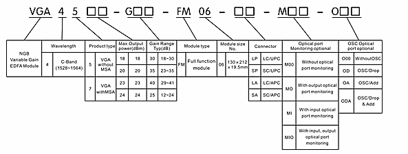
Ordering information

Related Items
|
10um series of optical fiber |
10um series of optical fiber |
10um series of optical fiber |
 |
|
|


 编辑
编辑