


ALL CATEGORIES
COMPANY INFO
LINKED


 编辑
编辑
Delivery Fee : $0.00
Quantity :
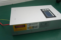
| Part NO. : | DCFBG-series |
| Datasheet : |

|
| Availability : |
IP16 Power Supply Instruction
|
Specifications |
Technical parameters |
|
Input voltage |
AC90V-AC250V |
|
Input frequency |
47Hz-100Hz |
|
Max output current |
32mA±1mA |
|
Efficiency |
≥89% |
|
Environmental |
working temperature :-20℃-40℃ |
|
storage temperature :-25℃-60℃ |
|
|
Humidity: 10%-95% non-condensing |
|
|
Control interface |
1.DB9 2.2EDG-5.08 |
|
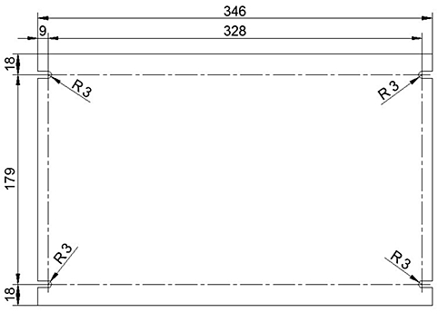
Dimension |
L*W*H=346mm×215mm×95mm |
|
Cooling |
Convection cooled |
• Wide Input Range (90~250v): it equals to put a voltage regulator and stabilizer in power supply, which can be used under different input voltages in different countries or outputs stabile current under instable input voltage.
• Short Circuit Protection: when positive and negative poles short circuits, power supply will cut off the circuit automatically for protection.
• Open Circuit Protection: when positive and negative poles open-circuits, power supply will cut off the circuit automatically for protection.
• Input Enable Signal Detection: show electrical signal from machine’s control board
• Temperature/Humidity Detection: self-protection starts when temperature or humidity is over permit value to ensure the safety of laser operation
• Working Status Detection: monitor electrical signal from laser tube in time and analyze its working status
• Malfunction analysis: analyze disorders by machines/ laser tubes and show that information on screen in different languages
• NOTICE: Please deal with the malfunction according to the given solutions showing in screen firstly.
Power supply can be used again only if it is powered off and restarted.
Wiring diagram
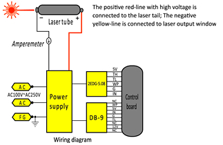
Wiring instructions
①
Footer 1 is 5V power supply. (Not needed when connecting the cardinal plate. It
is used when regulating the power with potentiometer and the 5V current should
be less than 20 mA.
② TH. TL refers to high and low power level respectively, and WP refers to
water protection.
③ Footer 5 G refers to ground, and 6 refers to input end.
④ When connecting the control plate, connect the light signal with footer 2 in
the case of high power level ligh emitting, (footer 3 for low power level
light-emitting), connect the ground-wire with footer 5, connect footer 6 with
power control analog signal, and make short circuit for footer 4 and 5.
⑤ For testing: 3, 4 and 5 are in short circuit (or 4, 5 are in short circuit
and 3, 5 are connected to switch), the potentiometer center is connected with 6
IN, and the two other ends are connected to 5V and ground (1 and 5)
respectively.
⑦ It is not proposed to control laser power with high- frequency modulation, because it will have impact on the service life of the laser.
⑧ The model is applicable to Z6 laser tube, it is necessary to regulate and use the current according to the laserinstructions.
⑨ The ammeter is concatenated to the cathode line.
Installation Diagram
Related Items
|
10um series of optical fiber |
10um series of optical fiber |
10um series of optical fiber |
 |
|
|
Prev product:No prev product Next product:325 and 442 nm Helium Cadmium (He Cd) Lasers |