
ALL CATEGORIES
COMPANY INFO
Delivery Fee : $0.00
Quantity :
| Part NO. : | DCFBG-series |
| Datasheet : |

|
| Availability : |
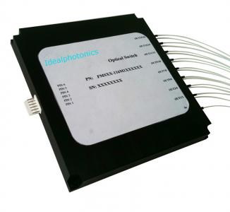
1xN Opto-Mechanical Switch
Feathure
Unmatched Low Cost
Low Insertion Loss
Epoxy-Free Optical Path
High Reliability and Stability
High Stability
Application
Configurable Optical
Networks
Fiber Optic Instruments
Optical Signal Routing
Testing Instruments
System Monitoring
Specification
|
Parameters |
Unit |
Value |
||
|
Center Wavelength |
nm |
1310, 1550, 1310&1550 |
||
|
Bandwidth |
nm |
+/-40 |
||
|
Configuration |
- |
1xN (N≤45) |
1xN (45 |
1xN (88 |
|
Insertion Loss |
dB |
≤1.0 |
≤1.6 |
≤2.0 |
|
Wavelength Dependent Loss |
dB |
≤0.25 |
||
|
Return Loss |
dB |
≥50 |
||
|
PDL |
dB |
≤0.10 |
||
|
Cross Talk |
dB |
≥50 |
||
|
Switching Speed |
ms |
≤10 (Sequence switch time of adjacent channel) |
||
|
Durability |
cycle |
≥10,000,000 |
||
|
Repeatability |
dB |
≤+/-0.05 |
||
|
Fiber Type |
- |
SMF-28 Fiber |
||
|
Fiber Tensile Load |
N |
5 |
||
|
Maximum Optical Power (CW) |
mW |
300 |
||
|
Operating Temperature |
°C |
0~70 |
||
|
Storage Temperature |
°C |
-40~85 |
||
1. Specifications are for device without connectors; Specifications may change without notice.
2. To add connectors, IL is 0.3dB higher, RL is 5dB lower.
3. Devices for higher optical power or with other type fiber or consigned fiber are also available.
Pin Configuration
DB9 Male Connector (Max.1x16):
|
Pin# |
Signal |
I/O |
Description |
|
1 |
D0 |
Input |
TTL, Channel Selection Bit |
|
2 |
D1 |
Input |
TTL, Channel Selection Bit |
|
3 |
D2 |
Input |
TTL, Channel Selection Bit |
|
4 |
D3 |
Input |
TTL, Channel Selection Bit |
|
5 |
/RESET |
Input |
TTL, L: reset to channel 0, H: Channel selection bit are effective |
|
6 |
/READY |
Output |
TTL, L=Ready, H=Not Ready |
|
7 |
ERROR |
Output |
TTL, H=Error, L=No Error |
|
8 |
GND |
Input |
Ground |
|
9 |
+5VDC |
Input |
5.0±5%VDC Power Supply (max550mA) |
DB15 Male Connector (Max. 1x32 ):
|
Pin# |
Signal |
I/O |
Description |
|
2 |
D0 |
Input |
TTL, Channel Selection Bit |
|
3 |
D1 |
Input |
TTL, Channel Selection Bit |
|
4 |
D2 |
Input |
TTL, Channel Selection Bit |
|
5 |
D3 |
Input |
TTL, Channel Selection Bit |
|
6 |
D4 |
Input |
TTL, Channel Selection Bit |
|
11 |
/RESET |
Input |
TTL, L: reset to channel 0, H: Channel selection bit are effective |
|
7 |
/READY |
Output |
TTL, L=Ready, H=Not Ready |
|
8 |
ERROR |
Output |
TTL, H=Error, L=No Error |
|
1, 9 |
GND |
Input |
Ground |
|
15 |
+5VDC |
Input |
5.0±5%VDC Digital Power Supply (max50mA) |
|
12 |
VM |
Input |
5.0±5%VDC or 12.0±5% Drive Power Supply (max500mA) |
|
10, 13, 14 |
NA |
NA |
|
DB25 Male Connector (Max. 1x128):
|
Pin# |
Signal |
I/O |
Description |
|
|
15 |
D0 |
Input |
TTL, Channel Selection Bit |
|
|
16 |
D1 |
Input |
TTL, Channel Selection Bit |
|
|
17 |
D2 |
Input |
TTL, Channel Selection Bit |
|
|
18 |
D3 |
Input |
TTL, Channel Selection Bit |
|
|
19 |
D4 |
Input |
TTL, Channel Selection Bit |
|
|
20 |
D5 |
Input |
TTL, Channel Selection Bit |
|
|
21 |
D6 |
Input |
TTL, Channel Selection Bit |
|
|
22 |
/RESET |
Input |
TTL, L: reset to channel 0, H: Channel selection bit are effective |
|
|
2 |
/READY |
Output |
TTL, L=Ready, H=Not Ready |
|
|
3 |
ERROR |
Output |
TTL, H=Error, L=No Error |
|
|
1, 10, 14, 23 |
GND |
Input |
Ground |
|
|
12, 25 |
+5VDC |
Input |
5.0±5%VDC Digital Power Supply (max50mA) |
|
|
13 |
VM |
Input |
5.0±5%VDC or 12.0±5% Drive
Power Supply |
N≤45, Max. 500mA |
|
11, 24 |
N≤88, Max. 750mA |
|||
|
N≤128, Max. 1000mA |
||||
|
4, 5, 6, 7, 8, 9 |
NA |
NA |
|
|
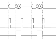
CHANNEL SLECTION TABLE
|
Optical Path |
Input |
|||||||
|
/RESET |
D6 |
D5 |
D4 |
D3 |
D2 |
D1 |
D0 |
|
|
RESET |
0 |
NA |
NA |
NA |
NA |
NA |
NA |
NA |
|
Com-1 |
1 |
0 |
0 |
0 |
0 |
0 |
0 |
0 |
|
Com-2 |
1 |
0 |
0 |
0 |
0 |
0 |
0 |
1 |
|
Com-3 |
1 |
0 |
0 |
0 |
0 |
0 |
1 |
0 |
|
··· |
1 |
··· |
··· |
··· |
··· |
··· |
··· |
··· |
|
Com-128 |
1 |
1 |
1 |
1 |
1 |
1 |
1 |
1 |
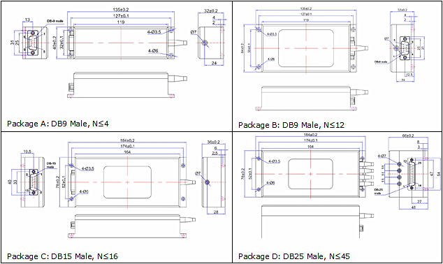
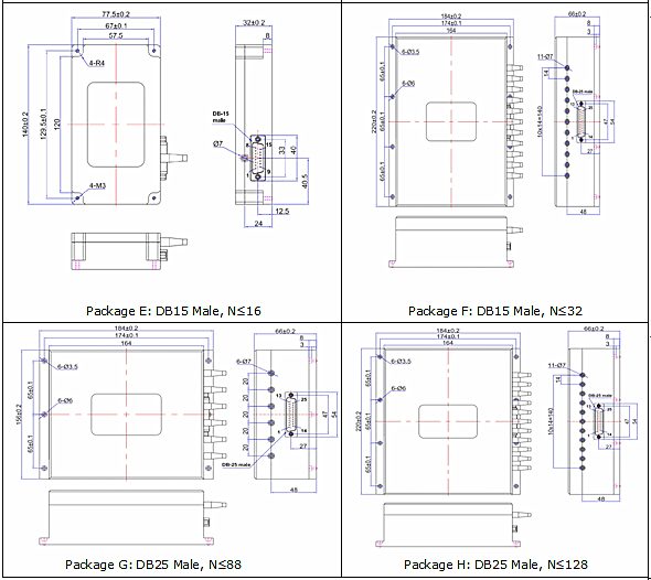
Package Dimensions
Ordering information
 Related Items
|
10um series of optical fiber |
10um series of optical fiber |
10um series of optical fiber |
 |
 |

|


 编辑
编辑