

ALL CATEGORIES
COMPANY INFO
LINKED


 编辑
编辑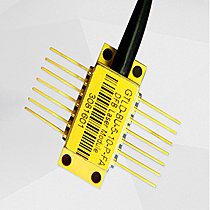
Delivery Fee : $0.00
Quantity :
| Part NO. : | IDP8981-1-xxx-0-0 |
| Datasheet : |

|
| Availability : | In store |
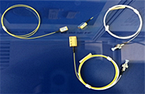
980nm Pump laser for EDFA

Idealphotonics,inc IDP8981-1-Series 980nm pump laser module is the pump source of Erbium-Doped Fiber Amplifier (EDFA). It needs higher output power and more strict reliability. In order to improve the product performance, we made some innovation. Firstly, the higher power 980nm pump laser chip is selected. Secondly, low-temperature glass soldering technology is used in the process of fiber lens fixing, chip soldering and other parts soldering. By all above this innovation, the stability and reliability is improved.
Applications● Low noise erbium doped fiber amplifiers(EDFAs)
● High bit rate, multicenter digital EDFAs
● Dense wavelength division multiplexing(DWDM) EDFAs for small package designs
● CATV system
Features
● 14-pin Butterfly Package
● With Thermoelectricity Cooling (TEC) and Monitor Photodiode (MPD)
● Single Mode Fiber(HI-1060) Coupling
● Excellent Reliability,to be fixed fiber with Glass Solder
● Telcordia GR-468-CORE Compliant
● RoHS Compliant
IDP8981-1-***-0-0(Under 200mW)
Absolute Maximum Ratings
|
Parameter |
Symbol |
Min |
Max |
Unit |
Test Condition |
|
LD Forward Current |
If |
- |
500 |
mA |
DC |
|
LD Reverse Voltage |
Vr |
- |
2 |
V |
|
|
TEC Operation Current |
Itec |
- |
2 |
A |
|
|
TEC Operation Voltage |
VTEC |
- |
4 |
V |
|
|
Storage Temperature |
Tstg |
-40 |
85 |
℃ |
|
|
Operation Case Temperature |
Top |
-20 |
70 |
℃ |
|
|
Relative Humidity |
RH |
0 |
95 |
% |
|
|
ESD Level |
- |
- |
500 |
V |
C=100pF,R=1.5 Ω, Human body model |
|
Lead Soldering Temperature and Time |
- |
- |
260 |
℃ |
≤10s |
|
Fiber Bend Radius |
r |
30 |
- |
mm |
|
|
Axial Pull Force |
- |
- |
5 |
N |
3x10Sec |
|
Side Pull Force |
- |
- |
2.5 |
N |
3x10Sec |
(BOL, Tcase=-25℃ to 70℃, TLD=25℃,-50dB reflection, unless noted otherwise)
|
Product Code |
Min. Operating Power (mW) |
Typ. Operating Current (mA) |
Max. Operating Current (mA) |
Min. Free Kink Power (mW) |
|
IDP8981-1-100-0-0 |
100 |
250 |
300 |
120 |
|
IDP8981-1-100-0-0 |
120 |
300 |
350 |
140 |
|
IDP8981-1-140-0-0 |
140 |
350 |
380 |
160 |
|
IDP8981-1-180-0-0 |
180 |
380 |
400 |
200 |
|
Parameter |
Symbol |
Unit |
Min |
Typ |
Max |
Remark |
|
Threshold Current |
Ith |
mA |
- |
45 |
|
|
|
Optical Output Power |
Pf |
mW |
100 |
|
|
|
|
LD Operation Current |
Iop |
mA |
|
|
400 |
|
|
LD Forward Voltage |
VF |
V |
|
|
2 |
|
|
Center Wavelength |
λc |
nm |
972 |
|
985 |
|
|
Spectrum Width |
∆λ |
nm |
|
|
10* |
RMS@-3dB |
|
MPD Responsibility |
Rm |
uA/mW |
0.5 |
8 |
20 |
|
|
TEC Current |
Itec |
A |
|
|
1.3 |
∆T= 50℃ Iop = 400mA |
|
TEC Voltage |
Vtec |
V |
|
|
3.5 |
∆T= 50℃ Iop = 400mA |
|
Thermistor Resistance |
Rth |
KΩ |
9.5 |
10 |
10.5 |
T=25℃ |
IDP8981-1-200-1-0
Absolute Maximum Ratings
(Note: Over Absolute
Parameter,May Laser Diode failure)
Parameter
Symbol
Min
Max
Unit
Test
Condition
LD Forward Current
If
-
800
mA
DC
LD Reverse Voltage
Vr
-
2
V
TEC Operation Current
Itec
-
2
A
TEC Operation Voltage
VTEC
-
4
V
Storage Temperature
Tstg
-45
85
℃
Operation Case Temperature
Top
-20
70
%
Relative Humidity
RH
0
95
℃
ESD Level
-
-
500
V
Human
body model
Fiber Bend Radius
r
30
-
mm
Operating Parameters
(BOL, Tcase=-25℃ to 70℃, TLD=25℃,-50dB reflection, unless noted otherwise)
|
Product Code |
Min. Operating Power (mW) |
Max. Operating Current (mA) |
Min. Free Kink Power (mW) |
|
IDP8981-1-200-1-0 |
200 |
650 |
250 |
(BOL, Tcase=-25℃ to 70℃, TLD=25℃,-50dB reflection, unless noted otherwise)
|
|
Symbol |
Unit |
Min |
Typ |
Max |
Test Condition |
|
Threshold Current |
Ith |
mA |
- |
50 |
|
|
|
LD Forward Voltage |
VF |
V |
|
|
2.5 |
|
|
Center Wavelength |
λc |
nm |
972 |
|
985 |
|
|
Spectrum Width |
∆λ |
nm |
|
|
1.0 |
RMS@-3dB with FBG |
|
MPD Responsibility |
Rm |
uA/mW |
0.5 |
8 |
20 |
|
|
TEC Current |
Itec |
A |
|
|
1.5 |
∆T= 50℃ Iop = 700mA |
|
TEC Voltage |
Vtec |
V |
|
|
3.8 |
∆T= 50℃ Iop = 700mA |
|
Thermistor Resistance |
Rth |
KΩ |
9.5 |
10 |
10.5 |
T=25℃ |
IDP8981-1-300-1-0
Absolute Maximum Ratings
(Note: Over Absolute Parameter,May Laser Diode failure)
Parameter
Symbol
Min
Max
Unit
Test
Condition
LD Forward Current
If
-
1200
mA
LD Reverse Voltage
Vr
-
2.5
V
TEC Operation Current
Itec
-
2.5
A
TEC Operation Voltage
VTEC
-
4.8
V
Storage Temperature
Tstg
-40
85
℃
Operation Case Temperature
Top
-20
70
℃
Relative Humidity
RH
0
95
%
ESD Level
-
-
500
V
Human
body model
Lead Soldering Temperature and Time
-
-
260
℃
≤10s
Fiber Bend Radius
r
30
-
mm
Operating Parameters
(BOL, Tcase=-25℃ to 70℃, TLD=25℃,-50dB reflection, unless noted otherwise)
Product Code
Min.
Operating Power (mW)
Max.
Operating Current (mA)
Min.
Free Kink Power (mW)
IDP8981-1-300-1-0
300
900
350
(BOL, Tcase=-25℃ to 70℃, TLD=25℃,-50dB reflection, unless noted otherwise)
Symbol
Unit
Min
Typ
Max
Test
Condition
Threshold Current
Ith
mA
-
80
LD Forward Voltage
VF
V
2.5
Center Wavelength
λc
nm
972
985
Spectrum Width
∆λ
nm
1.0
RMS@-3dB
with FBG
MPD Responsibility
Rm
uA/mW
0.5
8
20
TEC Current
Itec
A
1.6
∆T= 50℃ Iop = 950mA
TEC Voltage
Vtec
V
4.8
∆T= 50℃ Iop = 950mA
Thermistor Resistance
Rth
KΩ
9.5
10
10.5
T=25℃
Package Size
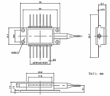
Note:
IDP8981-1-*** Series specifications in mm unless otherwise noted; tolerance=.x ±0.3,.xx±0.2
IDP8981-1-*** Series module pigtail consists of Φ250μm buffered,Corning
HI-1060 Single mode fiber. The length of fiber is more than 1m.
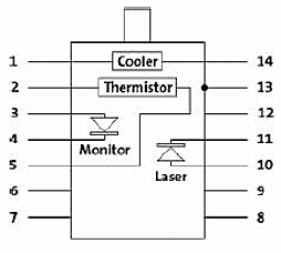
Package Information
|
1.Cooler(+) |
8.NC |
|
2.Thermistor |
9.NC |
|
3.Monitor Anode(-) |
10.Laser Anode(-) |
|
4.Monitor Cathode(+) |
11.Laser Cathode(+) |
|
5.Thermistor |
12.NC |
|
6.NC |
13.Case Ground |
|
7.NC |
14.Cooler(-) |
Ordering Information
IDP8981-1-***-*-*
IDP8
98
1
1
***
*
0
Idealphotonics,inc
Wavelength (nm)
Package Type
TEC
Power (mW)
FBG
Connector
IDP8
98:980
1:14 pin butterfly package
1:with TEC
100:100
120:120
140:140
180:180
200:200
300:300
0:without FBG
1:with FBG
0:without
2:SC/APC
5:FC/APC
Notice:
Do not put Laser transmission end (fiber cross section) to face toward your eye or skin. Active laser may burn your eye or skin.
Warning:
Absolute Maximum Ratings are not allowd to violate, otherwise, the product may be failure.
In the mode of CW, do not load an over-limit drive current, and do not directly turn off the electric power, otherwise, the product performance will be degraded. The right way to start the drive power is as below. Drop the device power voltage to “zero” status before correctly connect the product according to the pin-connection guide. Then slowly increase the drive current by monitoring the product output power.
Before installation,the product need to be smoothly fixed on the cooling radiator of the operation platform. The screw is M2.5. By this way, the bottom dissipation can be guranteed, and the product can work for longer time.
Do not knock by hard object at the product cover and tail tube. Do not strongly pull or wring the fiber.
ESD protection:
In the whole process of the product installation and working, system device and equipment need to have good earthing ( less than 2Ωof grounding resistance is recommended). Static control wrist straps are required for operators.
Related Items:
|
1310nm Superluminescent Diode |
High Sensitivity PIN-FET Receiver Module |
ICS-4000 PM Fiber Fused Biconic Tapering System |
 |
 |
|