

ALL CATEGORIES
COMPANY INFO
LINKED


 编辑
编辑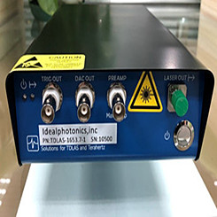
Delivery Fee : $0.00
Quantity :
| Part NO. : | TDLAS-ASL-A |
| Datasheet : |

|
| Availability : | In store |
TDLAS-1653.7-1 Benchtop TDLAS Integrated Controller

Description
Tunable Diode Laser Spectrometers are gas analyzer which provide a fast up date optical analysis.The TDLS line offers measurements for process gas, flue gas, impurity analysis, custody transfer, safety, with in-situ and extractive methods supported. The development of a sensitive sensor for detecting methane ( CH4 ) emissions biological samples is reported. The sensor is based on tunable diode laser absorption spectroscopy (TDLAS) using a continuous wave, thermoelectrically cooled Distributed Feedback Laser (DFB) and a 20m Fiber Coupled Herriot cell. A 2f-wavelength modulation spectroscopy technique was used to obtain DFB-based TDLAS CH4 emission measurements with an optimum signal-to-noise ratio. An absorption line at 6,047.046 cm−1(1653.7nm)was targeted to measure CH4 with a minimum detection limit of 1 ppm.TDLAS-1653.7-1 Benchtop TDLAS Integrated Controller Including the main functions as below:
A. Generate the Digital laser driven by the superposition of sine wave and triangular wave
B. Adjustable gain amplifier(AGA)、
C. 1f/2f Digital phase locked amplifier, analog output, temperature control unit;
D. Operating parameters and waveforms controlled and read by the computer terminal
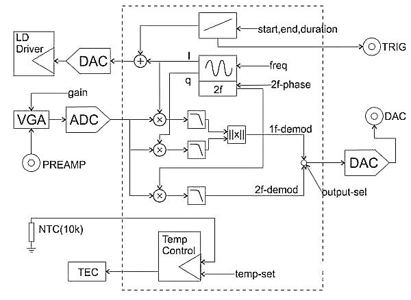
Functional block diagram of TDLAS Integrated Controller as follows:
Laser installation and selection:
Remove 6pcs M3 screws on the side of the instrument and open the upper cover. The butterfly laser is fixed on the corresponding hole position of the mounting plate with 4 M2.5 X6 screws. According to the pin definitions to Connect your laser diode. The optical fiber port is connected to the panel with FC/APC Senko Adaptor, and the fiber direction is constrained by the wire clip when necessary.
Here we suggest our customer user the laser diode Provided by idealphotonics in case the wrong handling with this device make all the system not work. We Strongly Suggest our Customer use NTT or Idealphotonics’s tested TDLAS DFB Laser diode in case any unnecessary inconvenience. Cause this two kinds Laser diode with high output power and work stability, what’s more without hopping mode. When fix the laser diode the fix board can be Rotating or turning over. All M3 holes can be used to install wire clips
Main Parameters:
|
Parameters |
Min |
Max |
Unit |
Remark |
|
Power Supply |
100V |
240 |
VAC |
|
|
Power Consumption |
5 |
15 |
W |
|
|
Frequency of Sin wave |
20 |
50 |
KHz |
|
|
Laser Driving Current |
0 |
125 |
mA |
|
|
Laser driving Voltage |
2.5 |
V |
@80mA |
|
|
Central Wavelength |
1649.9 |
1651.9 |
nm |
Typ 1650.9nm |
|
Line width |
1 |
10 |
MHZ |
Typ:3MHZ |
|
Tunable Range |
1 |
3 |
nm |
Typ:2nm |
|
Fiber Type |
SMF-28E |
|
|
|
|
Relative intensity noise |
-140 |
-150 |
dB/Hz |
Typ:-145dB/HZ |
|
Wavelength tuning over current |
0.008 |
0.012 |
nm/mA |
Typ:0.01nm/mA |
|
Wavelength tuning over temperature |
0.08 |
0.12 |
nm/℃ |
Typ:0.1nm/℃ |
|
NTC |
9.7 |
10.3 |
Kohm |
@25oC |
|
TEC Current |
-1 |
1 |
A |
|
|
Temperature Control Range |
0 |
50 |
oC |
|
|
Analog input (peak to peak) |
0 |
5 |
V |
AC coupling |
|
Analog output |
0 |
2.5 |
V |
|
|
Dimension |
22.5X15.0X6.5 |
cm3 |
||
|
Fiber Connector |
FC/APC |
|||
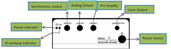
Control panel:
How to use:
Connect the power line with electric supply, and use the USB to connect the Personal Computer (Refer as Picture 1). Press the power switch button to open the controller. WIN7 and Windows system upper Win7 The system will prompt the automatic networking installation of USB drivers.When use other system or No Internet please down load the bellowing link: http://www.ftdichip.com/Drivers/VCP. Download the corresponding driver. When the driver is installed, the virtual serial device will appear in the "device manager".Open The TDLAS.EXE In Communication Port find corresponding virtual serial port. Click the Connect button,After a normal handshake, the console turns on and reads the current settings of the controller. Set the parameters in the GUI and Click the “Set Parameters”BUTTON Below Synchronize the parameters to the controller. Then Click Auto Run Button the device will work. Click Save All Parameters Save all the parameters in the controller
Before making the LD work, Please check all the parameters carefully make sure all the setting values in the working Range.
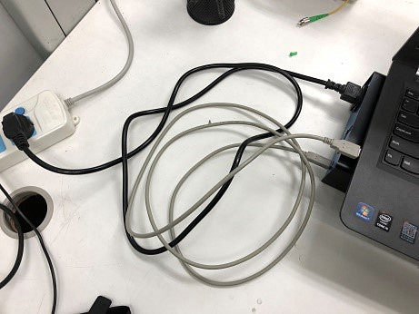
Pic1
1、Using an oscilloscope to observe the output of LIA
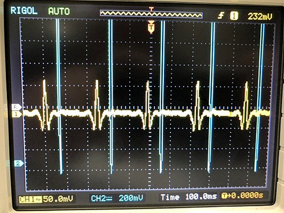
Pic2
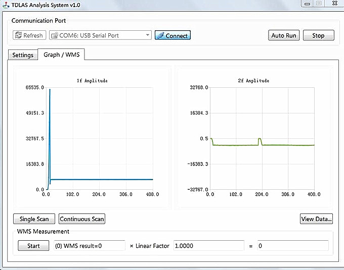
2、Obtain waveform through software
Set all the parameters well,and make sure the controller not in the Auto Run state, enter the Graph page, Click the Single Scan Button,The controller will begin a single scan and display the 1F and 2F demodulation results in the diagram. Clicking on Continue Scan will begin to scan continuously, and all the waves will be uploaded after each scan. Because of the time of communication, the time of scanning interval is not definite. Clicking again will stop running.
3、WMS calculation
In Graph page, ”WMS measurement” Click start button,The controller will automatically scan it several times and try to analyze the absorption peak amplitude information in the waveform, which takes about 6-15 seconds in total. The analytical effect is related to the selection of laser, the setting of optical path and the experimental parameters. The result range is 0~50000. Users can set linear coefficients in Linear Factor to fit the actual experiments.
TDLAS Software GUI:

Related Products:
1. 1650.9nm DFB Laser diode
2. LIA
3. 20m Fiber Coupled Herriot cell
4. CH4 TDLAS Integrated Systems
Ordering Information:
|
TDLAS |
- Absorption spectrum line |
- Algorithm |
|
1653.7-CH4 |
1-with |
|
|
1512.18-NH3 |
0-Without |
|
|
1567.12-CO 1578-CO2 1392-H20 1742-HCL ....... |